Ever since I've had this bike it's had an oil leak from the right-hand cover when standing on its centre stand. Tipping the bike to the left on the side stand slowed the leak considerably. I had attributed this to a poor rh case gasket seal... Potentially a warped cover so I made a thicker gasket from some nitrile sheet. This seemed to stop the seepage from the cases but oil continued to appear in practically the same quantity beneath the bike. Now however oil was clearly emerging from the kick-start shaft.

This strikes me as unusual. There are quite a few reports of the bike leaking from the rhs case when running, usually around the gear change or kick-start shafts. However these don't seem to fit my problem which develops on standing, not running. Running reduces or eliminates it. There is in fact no requirement for any oil between the rhs cases as there's nothing there that needs running lubrication. However, crankcase pressure is vented through the camshaft and distributor breathers into the case space and this will carry a little oil with it. Add to that any small leakage from the gear change or kick start and a small amount of oil can end up there. To prevent it from becoming too much the oil can flow through a communication passage back into the crankcase and from here it will be scavenged with the rest and pumped up to the tank. You can buy a blind bearing for the camshaft which blocks off the camshaft breather which is not actually needed as a distributor breather also performs this job. There is also a modified gear change cover plate which should prevent oil entering the rh case along the gear change spindle. I don't think either would directly solve my problem although they can't hurt.
At the moment my working hypothesis is that this is a wet sumping problem. On standing my bike rapidly empties its oil tank into the motor. Oil collecting in the crankcase could then pass backwards through the scavenge portal and eventually reach the same level in both crankcase and rhs case. If this level is above the kick-start shaft then oil will exit along the shaft which has no seal. The gear change lever is actually lower but leakage here is less obvious as the lever has a felt seal. Obviously I can manage this problem by using the side stand effectively to raise the level of the kick-start, or reducing the amount of oil in the motor, but neither is satisfactory. I removed the spark plug and operated the kick start to return oil to the tank. I found that the leak stopped but reappeared within 15 minutes! This is a really fast wet sump!
Wet sumping is caused by oil flowing downwards under gravity and through the oil pump. The pump is actually two pumps in one. The first sucks oil through the mesh filter at the bottom of the tank and delivers it under pressure to the crankshaft, rockers etc. This oil passes through the motor's various oil ways, losing pressure as it does so and eventually collects as a pool in the bottom of the crankcase. From here the second pump scavenges the oil pumping it back up to the top of the oil tank where the process will be repeated. Each part of the pump is designed to pass oil in one direction only, and only when the motor is running. However this valving function is achieved via ball bearings seating in a conical depression under pressure of a spring. It's not perfect even when new, and dirt or damage to ball or seat, or weakness in the spring would then allow oil to flow slowly through the pump under gravity and back into the crankcase. I suspect my oil pump needs attention to improve the check valve function, anything from a new gasket, springs and balls to complete replacement may be necessary.
Usually, before starting any strip I would drain the oil. In this case I want to see how it is getting into the rhs case, so I pumped it back to the tank using the kick start and then started to remove the rhs cover.
Its clear that this can't be removed because its jammed up against the rhs footrest. This can't be removed because its jammed against the exhaust so the first step has to be remove the exhaust, loosen the footrest and then remove the kickstart and gear change levers.

 |
| Cover up against footrest, footrest nut against exhaust |
To remove the exhaust loosen the finned collar with an imperial sized Allen key and slide it away from the head

Loosen the footrest nut and slip the exhaust off the stud. Refit the footrest to keep the nut in place.
 |
| Loosen footrest and release exhaust mounting bracket |
You can then rotate the exhaust (carefully) and ease the exhaust down pipe forwards off the collar screwed in the head in order to remove the whole system. There wasn't actually enough room to remove the finned collar but that's not a problem, it can stay there.
 |
| Collar remains jammed on the frame downtube |
Loosen the footrest nut and fold the footrest down and out of the way.
 |
| Loosening the footrest... |
 |
| ...and folding it down |
The next step is to remove the kick start lever which is retained by a cotter pin and nut- note this is a true cotter pin with a flat on the shaft and a retaining nut. Not as our American cousins would say, a split pin! So Loosen the nut...
... and tap out the pin. I unscrew the nut until its flush with the end of the pin to protect threads. You can then place a large hammer against the kick start as shown to absorb the shock and tap the nut end with a smaller hammer. The pin should move and any excess force simply pushes the larger hammer away.
With the kick start off, I removed the gear change- a simple process, undo the nut and then unscrew the bolt entirely and remove it before pulling the lever off.
 |
| Remove the lock nut and unscrew the bolt (remove it entirely) before pulling the lever off |
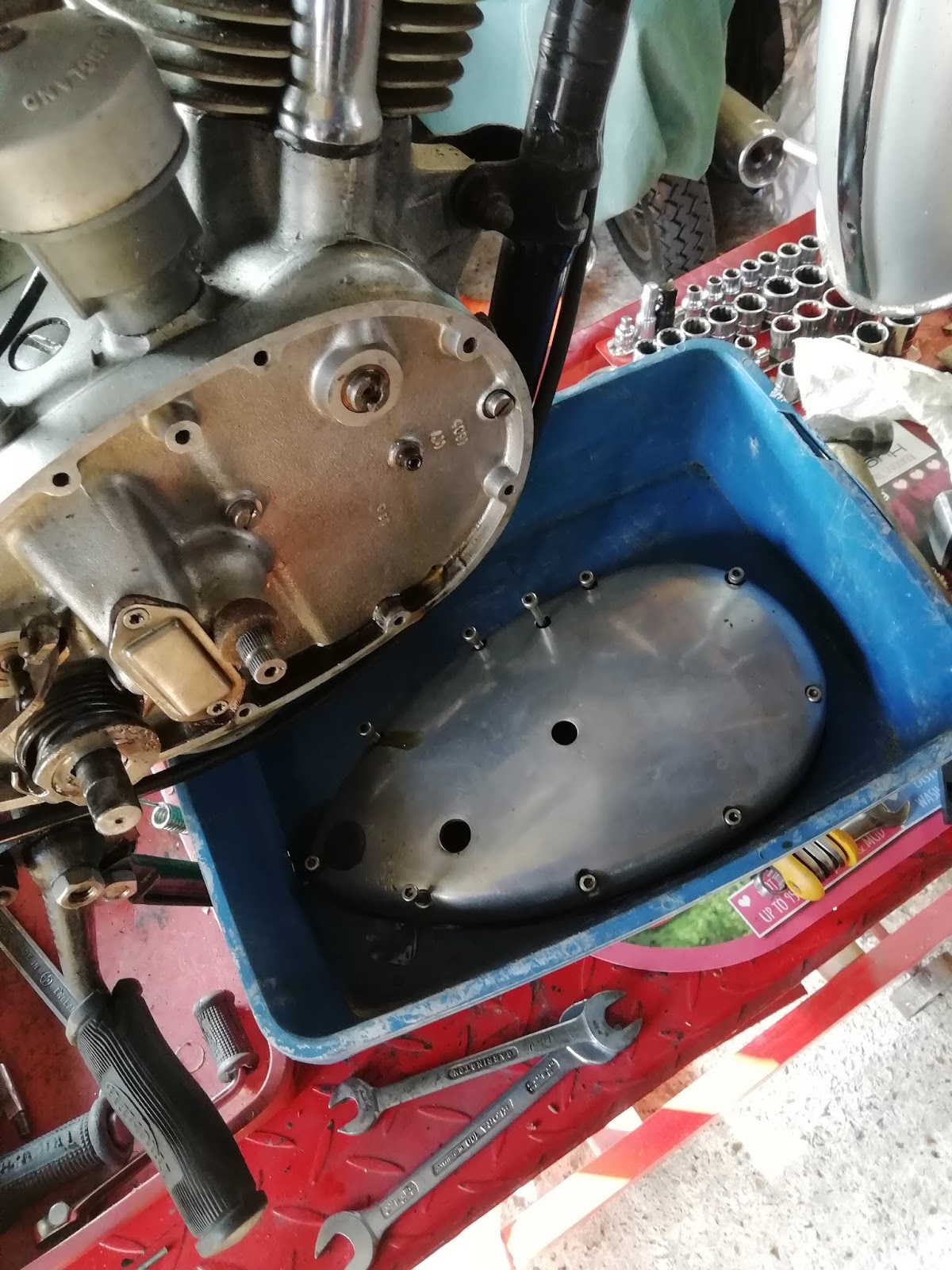
I temporarily refitted the kick start in order to pump oil back up to the tank and then loosened all the Allen screws (on my bike) before easing the case forwards with its gasket- this was a nitrile gasket I made earlier and should be reusable so I wanted to save it. Remnants for the oil drained from the case (as I hadn't drained the motor first)
 |
| Oil drains from the case as its eased forwards. |
This also leaves all the screws in their correct locations so I simply placed the whole cover in a try for storage.
 |
| Cover screws and gasket stored safely. |
This exposes the inner case.
 |
| Inner case as revealed. Note felt seal on the gearchange lever... |
 |
| That just slides off. |
At this stage I could observe the origin of the oil leak. I operated the kick start again by hand and detected puffs of air from the camshaft and distributor breathers. Both of these were at the top of the motor and didn't seem to be accompanied by any great oil movement (although this may be more evident when the motor is running).
 |
| Camshaft breather hole in side of camshaft mounting boss (mid picture on left) Distributor breather is behind this near the top of the case. |
As I waited a flow of oil; was seen clearly emerging from the crankcase at the communicating (scavenge) hole near the bottom of the case.
 |
| Oil progressively seeping from scavenge hole |
I think this shows that there is no problem with oil production by the breathers but the problem is as I suspected excess oil entering the crankcase under gravity from the oil tank. I cant tell what's causing this but clearly I need to dismantle further to investigate. I don't want to disturb the gearbox or timing gears and camshaft as I remove the inner cover. This should be possible provided that I loosen all attachments and take care to press them backwards as I ease the cover forwards. However this will expose the gearbox and crankcase cavities so its now time to drain the oil from both.
The crankcase drain plug can be accessed fro the left hand side of the bike
 |
| Crankcase drain plug (centre) |
The gearbox combined level and drain plug is access from the right but is positioned tightly against the oil pipes.
 |
| Combined gearbox and level plug sandwiched between frame tube and oil pipes |
Access to both could have been easier and both had obviously been abused in the past such that sockets couldn't slip over them. I removed them with C spanners and opted to try and clean up their profiles at a later date. I drained the oil from both compartments and then started to remove the cover. The main attachments to remove are the clutch cable, kick start spring and gear change quadrant.
Loosen the clutch cable at the handlebar end and then pull the cable nipple from the clutch arm fork using snipe nosed pliers. There is a small ball bearing in the cup of the clutch operating lever- remove this and keep it safe. The clutch won't work without it.
 |
| Releasing the cable nipples from the clutch arm watch for the ball bearing in the arm cup. |
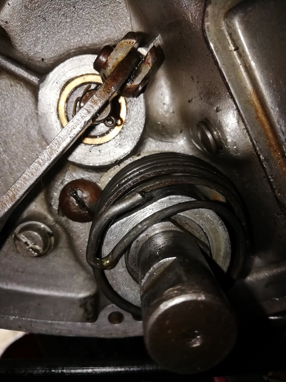
I could then release the kick start spring. Wearing gloves in case of excess spring pressure, twist the tabbed washer against the spring and rotate it to align the washer and shaft flats. The tabbed washer can then be removed.
 |
| Kickstart spring retained by the tabbed washer |
 |
| Rotating the kick start washer to release spring pressure. |
The other end of the spring is fixed by a screw
Release the screw to slip the spring off the kick start shaft
 |
| Loosening the spring retaining screw to remove the spring. |
In order to remove the gear change quadrant its necessary to remove the cover plate. I used an impact driver- not because the screws were tight but because their heads had been damaged. There should be serrated washers beneath these screws too but they were missing. I'll replace the screws with new and add washers in the rebuild.
 |
| Gearchange cover plate |
Cover removed revealing the crushed cork gasket behind. The tip of the gear change quadrant is then visible. Its retained by a pin which is itself held in place by a split pin.
 |
| Quadrant pivot pin and split pin retainer. |
 |
| close up |
Its a bit tricky but the pin can be straightened and removed. It is possible to break the pin legs off, this is easier but take care not to drop parts into the gearbox, or if you do, remember to remove them later.
 |
| Straightening the pin legs... |
 |
| ... and removing the pin. |
The pivot pin can then be withdrawn
 |
| loosening the pin |
 |
| Pin removed! |
The inner case is then held on by three large cheese head screws and one small Allen screw.
 |
| Rear and centre case screws- indicated by little finger and index |
 |
| Front case screw. Note the small Allen screw to the left of the front case screw. |
I loosened all 4 screws and eased the inner cover forwards. This is retained by flange sealant so it was a bit tight. It is REALLY important to push all the movable bits- the kick start, gear change shafts, the quadrant and the camshaft backwards as the cover comes forward. I knew this and even I fell foul of disaster. I was pulling the cover and pressing all those items above backwards with my thumbs at the same time. However, it is not sufficient merely to press the camshaft with your thumb. I had not realised it but this simply presses the camshaft flush with the cover... and as the cover comes forward the camshaft also comes forward with it! Disaster. If doing this again I would use a small socket under my thumb and on the camshaft so that I could actually press it backwards and
through the cover, not simply flush with it.
Well sadly I didn't do this and the camshaft was pulled out of engagement with the timing gears.
This was catastrophic and the cam followers came off the cams. I now have no alternative but to remove the head and reset the valve timing from scratch. In fact this is only another 4 bolts but its a complication I had definitely intended to avoid! I will write another post concerning how I actually get on with this effort.
Refit the distributor clamp bolt to avoid messing the timing up too badly! You will need to use sockets to pack it out so that it can be ti.ghtened up against the clamp
In the meantime I renewing my efforts to account for this awful oil leakage. I suspected I would find something wrong with the pump or a lack of a gasket. I removed the pump- its only 2 bolts, 1/8WW. I did find that they were unexpectedly stiff and couldnt be turned by hand
The pump came away easily enough once the bolts were out. There were two balls in the rear, the springs here had remained in the case.
 |
| Oil pump removed. This is the rear, note the ball bearings in the rh holes. |
The gasket was left in the case and the springs were also left there. It might be a clue to my problem but this gasket was soaked in oil.
 |
| Gasket still in case, finger indicates the two springs left in the case. |
I dismantled the pump and found nothing obvious but the springs seem very puny. I could see no debris inside the pump and the balls appeared undamaged.


However I did find that the bolts were very tight in the body of the pump. Although the bolts would enter the pump body from the top, they would not exit at the base and needed to be rotated. This effect had actually cut a thread in the body. This cannot be right and I suspect that this effect has led to a "cross threading" effect where although the bolts were tight, they had actually tightened the threads in the case against the artificial threads cut in the body by screwing the bolts through the tight spot. This would in turn have prevented the pump from seating onto its gasket, potentially allowing oil leakage. I was able to run an imperial 5/16" drill through the pump screw holes by hand. This opened up the passage and allows the bolts to slip through the pump unobstructed, and thus pull it down evenly and seat it firmly onto its gasket. In addition I have ordered new springs and balls to rebuild the sealing action.
 |
| Balls and springs as supplied. Note that although the balls are different sizes, the springs are the same. |
In fact his raises a query because the balls are two different sizes. There are diagrams n both Haynes and the Triumph parts book and both of these show the larger balls inside the pimp with the smaller ones behind. However both texts and legends identify the balls n the pump as the smaller and those behind as the larger! They cant both be right. I put this out on the web and got straightforward contradictory advice! I will simply go with the text not the illustrations and put the bigger balls behind.
In th e meantime I cleaned up the gasket surface. One possible source of problems seemed tome to be the gasket itself. Looking at the pic above it seemed that the holes punched to accommodate the springs and balls were encroaching on the holes in the casting. This might cause the springs to catch on the gasket so that some of their compressive force was taken off the ball bearings. The edges of the gasket are a bit mashed around the holes suggesting that this might also have been happening.
I cleaned up the casting surface
...and punched a wider hole around the spring slot in the gasket.
This avoids any potential for the spring to catch on the hole. The bottom hole seems to match up better so I may not need to enlarge that one. Having dismantled the pump it seemed daft not to renew the springs and balls so I went ahead- the LARGER balls go in the pump body. There is a fair bit of misinformation out there (some of which is mine) but this is the correct way round fit the balls; larger balls in the pump body, smaller balls in the engine case and behind the pump..
Drop them in and seat them with a light tap from a drift- should really be aluminium but I didn't have one so gentle with the steel.
You can then add the springs and screw in the plug caps. To fit the balls in the engine I fitted the gasket and slipped the springs into the relevant holes.

... and then I used oil soluble assembly lube to stick the smaller balls onto the back of the pump
... before offering it up carefully and screwing it into place. I'd have liked to test it but this would mean turning the motor and given the gearbox problems I had before I'm not about to risk the gears jamming again. The best I could do was add oil to the tank and see if it once more seeped down into the cases. Luckily there was no such seepage even when left overnight. Of course this isn't a fair test; there might be an airlock in the oil feed pipes but it was the best I could do and at least it gave the right answer. To be fair if there was a leak I would have expected any air lock to dissipate that way as well so hopefully this means all is OK.
I went ahead to fix the inner cover into place. Carefully cleaning up the mating edges of both crankcase and cover before using flange seal in a thin coat to the mating edges of the cover only.
 |
| I used Loctite flange sealant- I'm guessing there are a number available but I think its important to use a flange sealant which compresses to almost nothing as an instant gasket could affect end float in the gearbox.. |
Its a bit tricky to fit the inner cover; you need to support the shafts to align them with the holes in the cover and I found the kick start tended to foul it as the cover goes back. I rotated the kick start until I found a position where the cover could slide back relatively easily. For reference this means setting the kick start pawl between 5 and 6 O'clock before offering up the cover. You may need to operate the gear lever a little to move the end of the quadrant into a position where it will emerge through the slot in the cover. You can then orient the split pin holes in the quadrant and the retaining pin roughly and insert the pin. You may need to press the quadrant back against the spring levers at the back of the gearbox to align the pin hole with the case. Once the pin is in I used a 90 degree pick to align the split pin hole in the pin with that in the quadrant more accurately.
 |
| Using a 90 deg pick to pull and push the split pin holes into alignment. |
 |
| Holes aligned |
Fitting the retaining split pin is a little awkward- I found it easier if you bend it slightly
 |
| Bend a new split pin into a slight curve |
It then slips through ...
 |
| and slip it inot the spilt pin hole. If these are aligned it passes through OK |
 |
| and you can pull it down with some pliers. |
...and you can pull it the rest of the way down using some snipe nosed pliers.
Use the pliers again to bend the arms over.
 |
| fold up the arms |
I then reftitted the cover plate using a new gasket and new screws to replace the mullered originals.
 |
| Refit quadrant cover, new gasket cork and screws. |
Refit the clutch cable. DO NOT FORGET the ball in the lever cup or the clutch will not be adjustable.
 |
Kick start spring refitted, clutch cable fiddled through its hole and about to connect to the lever arm (Don't forget the little ball) |
The rest of the assembly really went as the revers of disassembly. I refitted the kick start spring and its washer as above and finally refitted the front rhs cover. One problem was that both the gasket sets (nos) I had bought turned out to have shrunk over time and neither gasket fitted. I therefore cut another nitrile which gave me a good fit before fitting the case. At this stage I had by now refitted the cleaned carb with its new float needle and replaced the cylinder head. Neither of these had actually needed to be removed in order to sort out the oil pump, but in my case both needed some sort of attention either because of earlier problems or my own ham-fistedness! I replaced the exhaust, reset the tappets and fitted the footrests and foot control levers
Finally, I filled the gearbox with oil and kicked the motor over until I got oil return to the tank. This did take a while and panicked me at first! I detached the oil return pipe at the tank to fill it with oil in case it was air locked. I also squirted engine oil through the crankcase front plug towards the rear of the pump. Eventually I got oil return. I refitted the spark plug, applied the tickler- turned on the ignition and kicked the motor over. Gratifyingly it started first time and there is no sign of the kick start oil leak. I'm calling that a success!


Well explained Mike, thank you should help a lot of people.
ReplyDeleteGlad you found it helpful.
ReplyDelete